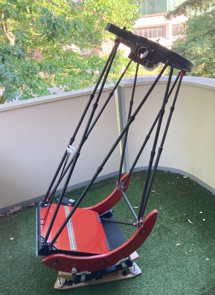
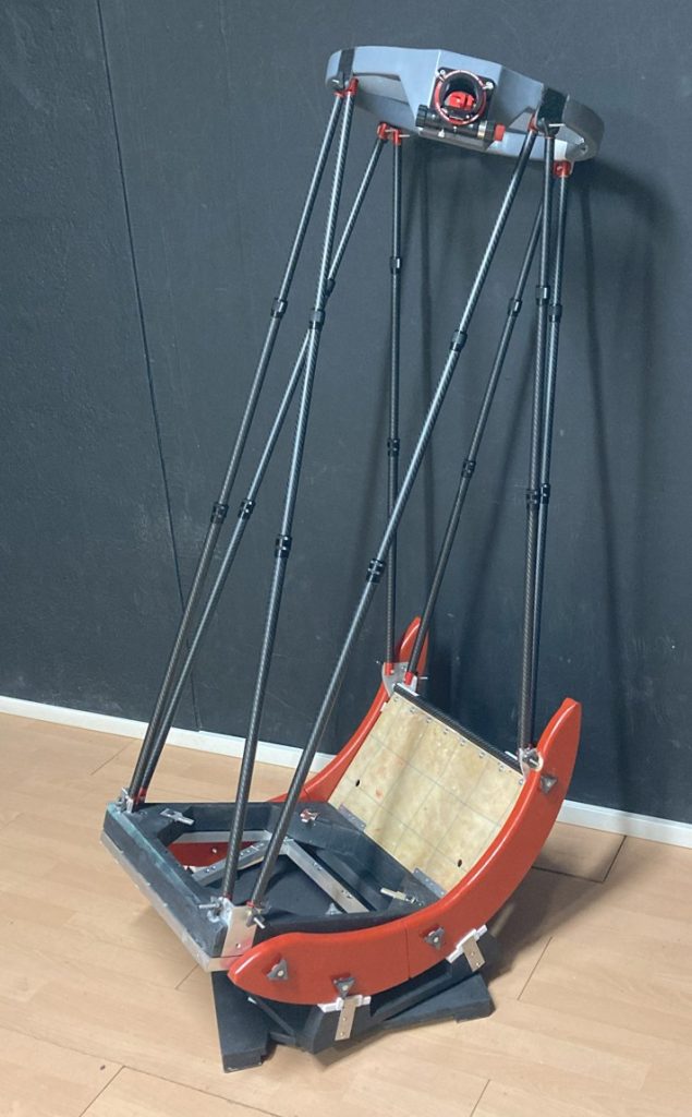
On this page you’ll find explanations and details of the construction of the T400 and its equatorial table. This build took place over nearly 18 months, in intermittent phases. The challenge was to achieve first light at the NATs and conduct intensive tests during the Astrociel 2025 meetings.
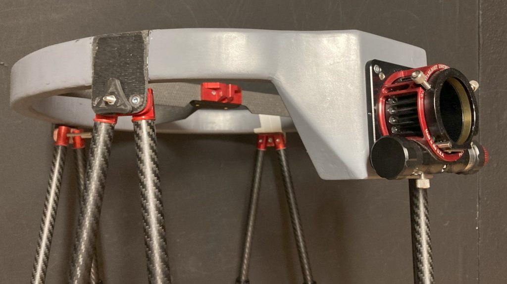
Secondary cage
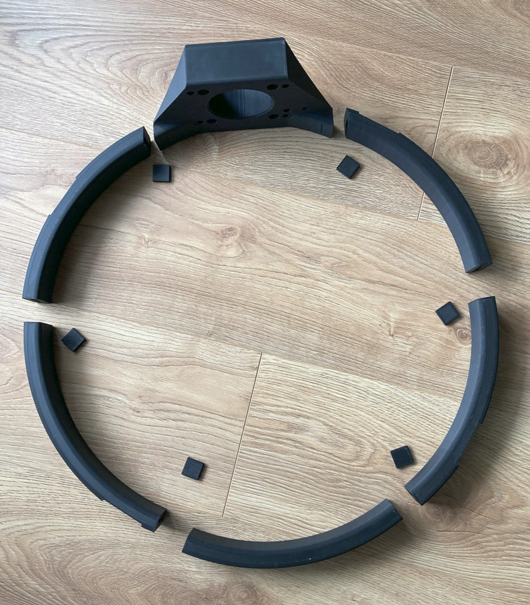
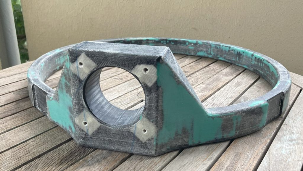
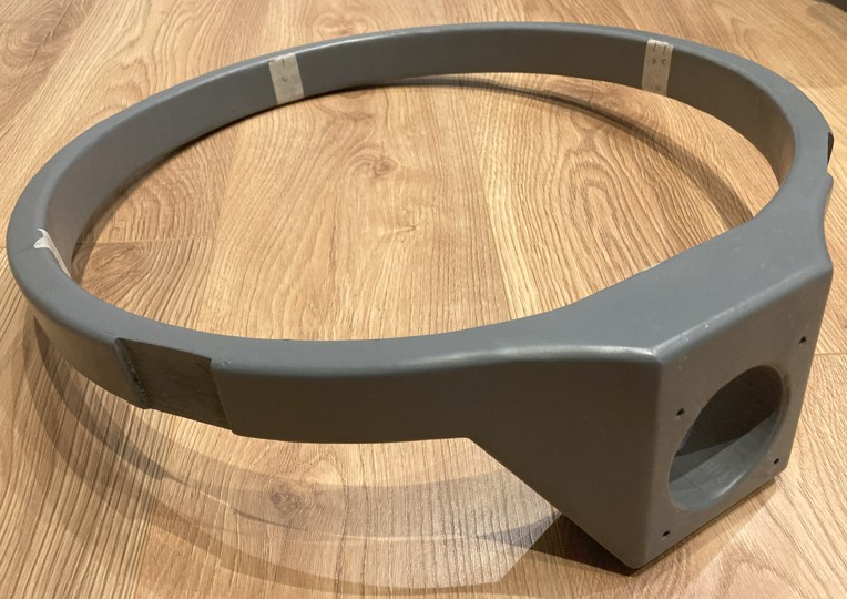
The core of the secondary cage was 3D-printed using high-speed PLA filament with annealing. Since the print bed was too small, the cage was divided into 6 sections, then dowelled and glued together. The plastic core was vacuum‑laminated with 100 g/m² fiberglass twill cloth.
On the first attempt, vacuum + 60 °C curing was too harsh for the thin (1 mm, 10% infill) walls. On the second attempt, walls were thicker (1.5–2 mm, 10%), and vacuum and curing were done separately, resulting in slightly heavier assembly.
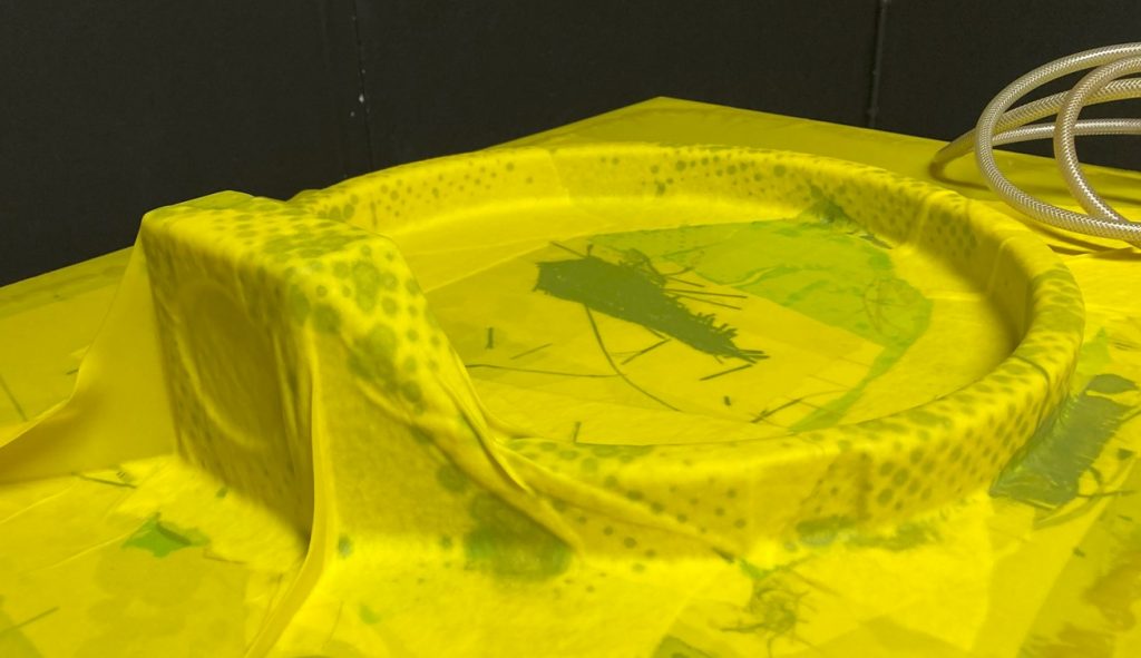
The already rigid core was laminated in two stages using U‑shaped overlapped forms.
Initial sanding revealed surface flaws that would show under paint, so the surface was treated with auto‑body filler (green), then grey primer, and finally matte black paint.
Spider assembly
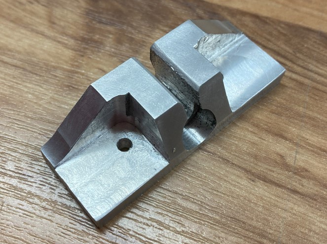
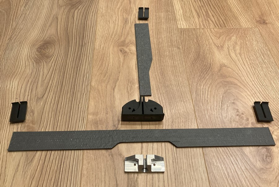
The primary mirror support uses a ball-on-screw interface. Initially planned as a 3D‑printed piece, it was deemed too fragile to support 500 g above the primary mirror, so it was machined from aluminum.
The spider vanes are composed of two 16 × 2 mm flat bars laminated together into a 32 × 2 mm final structure, with carbon fiber plies on both sides. The rest of the spider consists of 3D‑printed parts. To position the spider accurately, the secondary cage was placed flat, aligned with a collimation laser, and verified that the set screws at the focuser base were unused for centering.
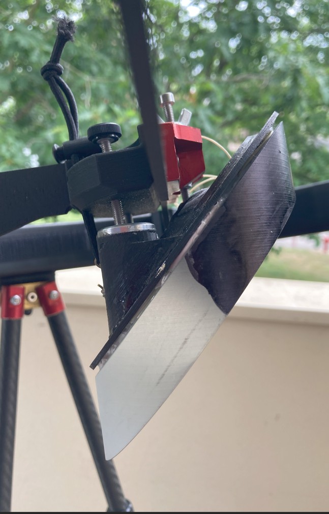
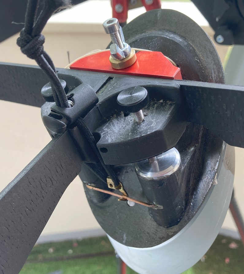
Secondary mirror mount
The ball housing to form the pivot was 3D‑printed, then epoxy‑bonded onto a 2 mm carbon plate. The mirror is glued using three silicone pads. It is mounted to the spider via a stop under a Nylstop nut, a conical washer, and a butterfly nut for centering and tightening.
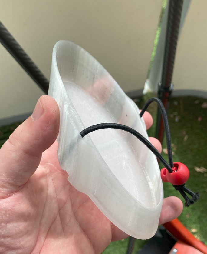
An elastic round seam + X‑hook + cord clamp holds the mirror against the collimation screws; the elastic is carried by the spider’s rear vane. Though simple, this setup is highly effective. Since the mirror is removable, a compact 3D‑printed cap protects the mirror’s optical surface.
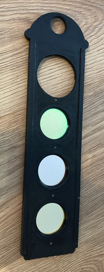
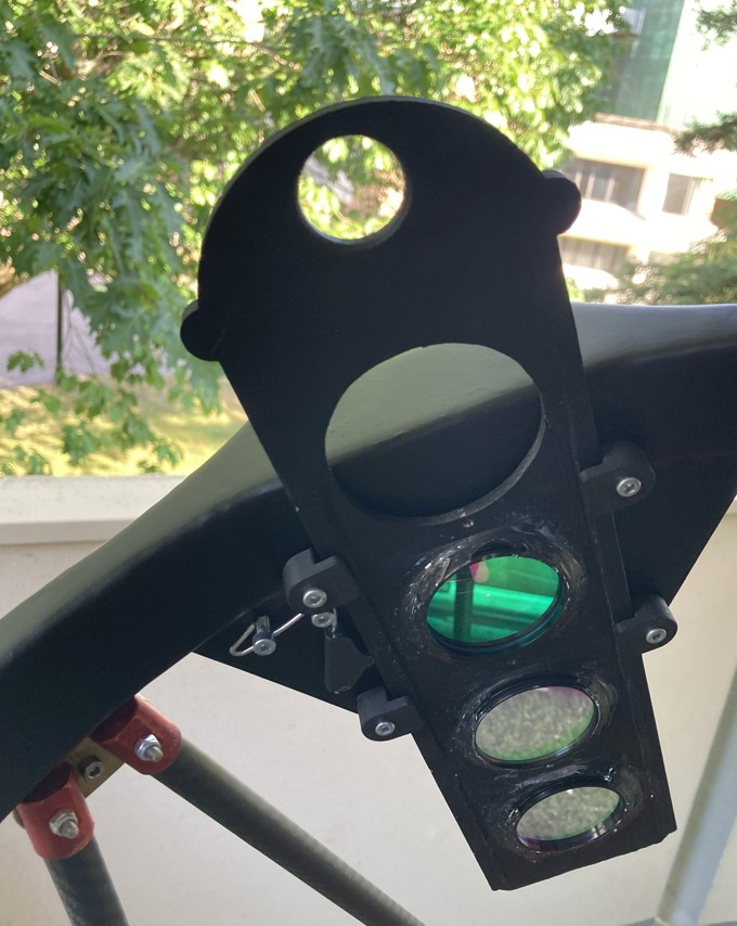
Filter slider
The filter slider is made from 2 mm balsa board with carbon strips on each side, plus a bit of 3D printing for friction points and filter support.
After trying several locking systems, filters are silicone‑glued in place.
Rails are simple L‑brackets screwed into the cage; the locking mechanism is a large paperclip around two screws, with a 3D‑printed “push button”.
The no‑filter position is at top to avoid exposing filters to dew. UHC, OIII, and HB filters reside under a ring exposed to the observer’s breath, protected by a skirt.
Tubes
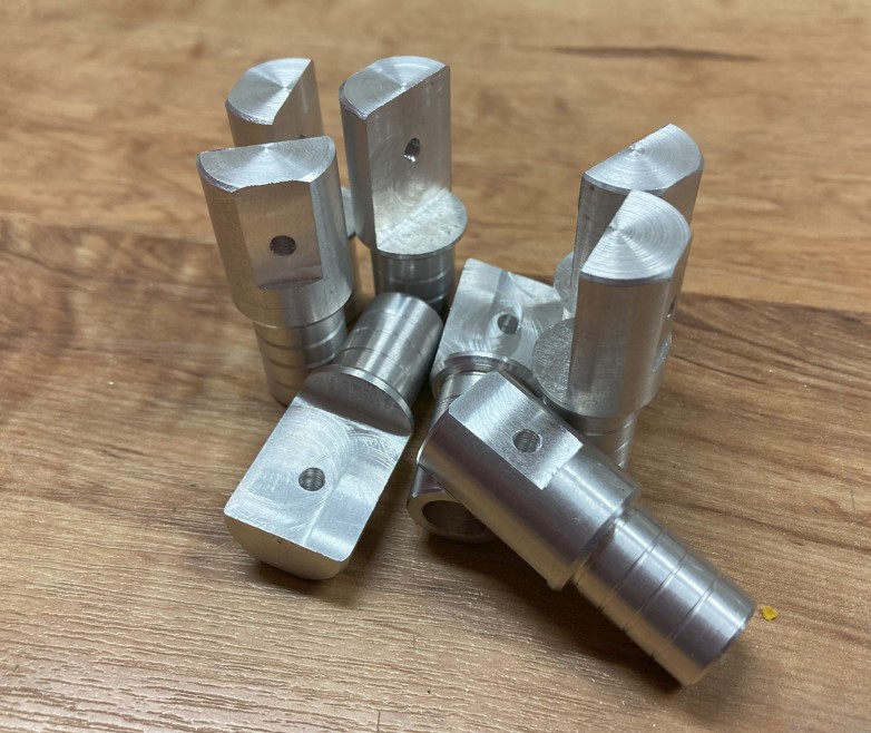
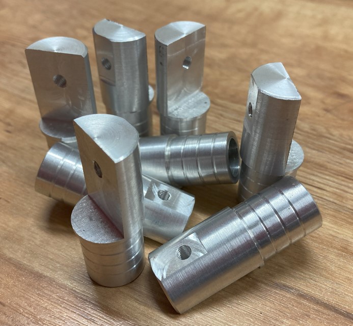
Machining / Turning
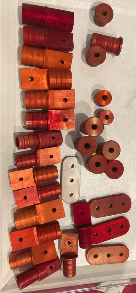
Before working with messy fiber materials, aluminium parts were turned: 16 caps had to be made (8 of 20 mm diameter, 8 of 16 mm).
A handy tip: a 3D‑printed jig was used for drilling the caps to avoid mistakes.
Anodizing the caps
Anodizing proved tricky without consistent alloy or process.
Final procedure developed:
Clean with “Tifoo” anodizing activator, rinse 5 min.
Anodize 1 hr at 20 °C with 0.5 A current, rinse with distilled water.
Dye with Dylon pagoda‑red at 40–50 °C for several minutes, taking a darker color to account for fading.
Fix the dye by boiling for extended time—2 hrs with intermittent re‑boiling (every 30 min).
Resulting colors vary due to alloy differences and varying bath conditions.
Tube assemblies
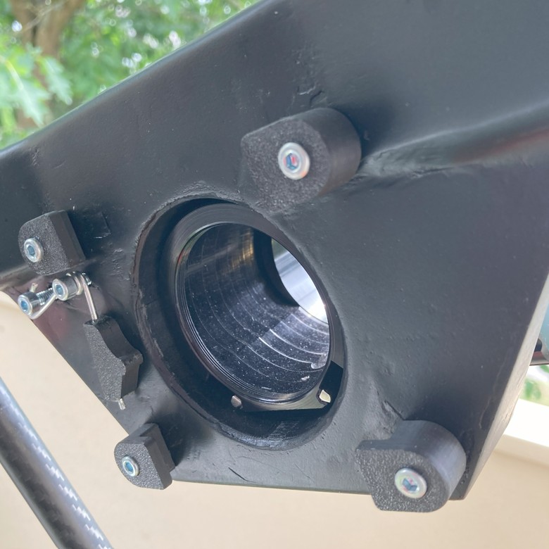
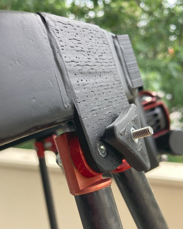
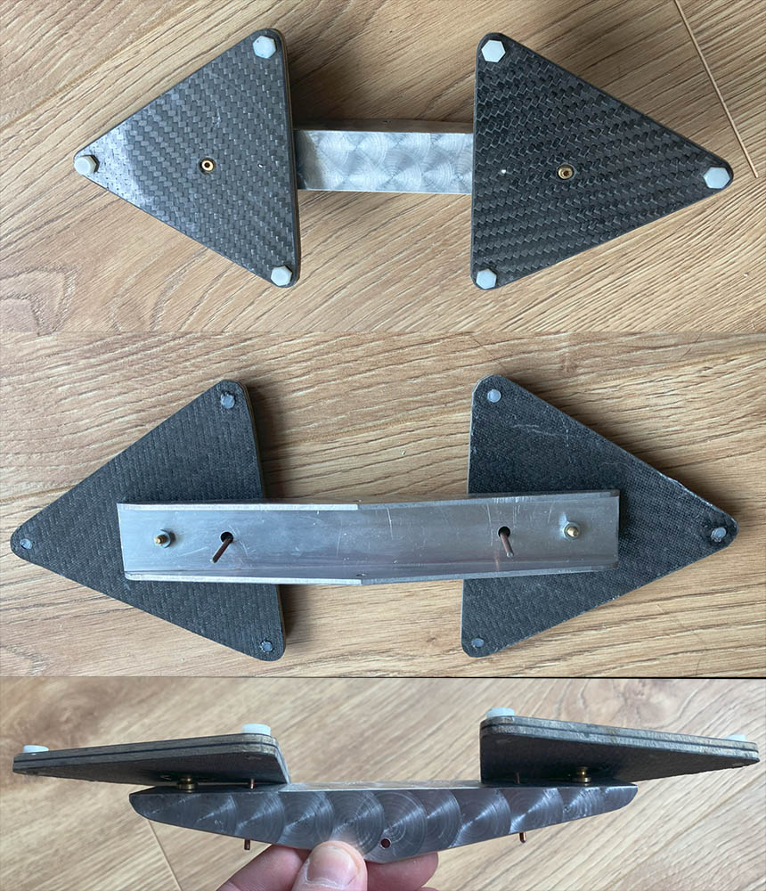
The upper struts are fixed to the secondary cage via a carbon bracket; screw heads act as locking pins with 5 degrees of constraint, the sixth via a clamp screw. This design works very well.
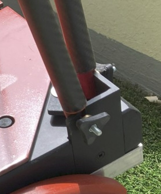
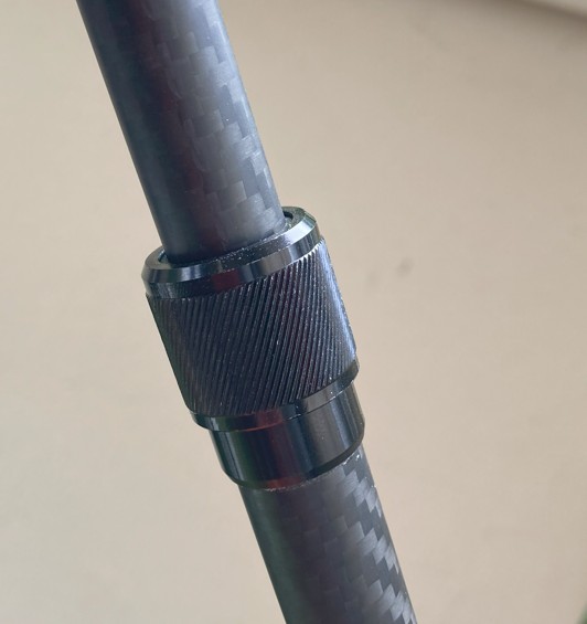
The lower fixings are classic: caps in a forked aluminium bracket, tightened with a nut and conical washer. Tubes are telescopic and clamp with annular clamps.
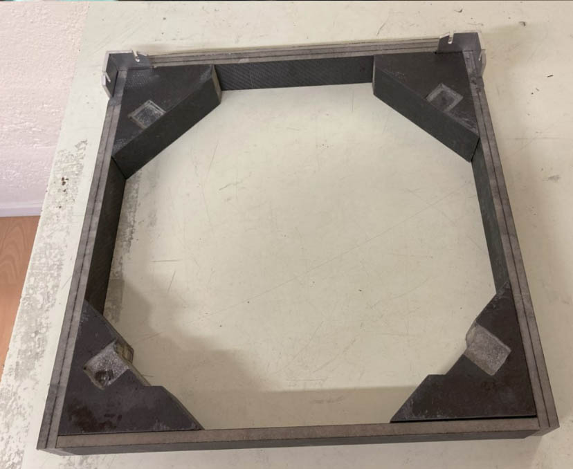
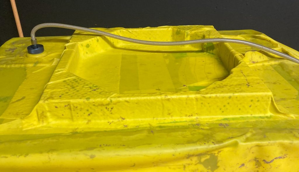
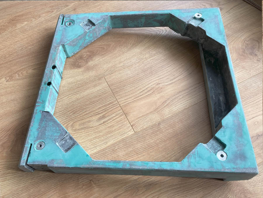
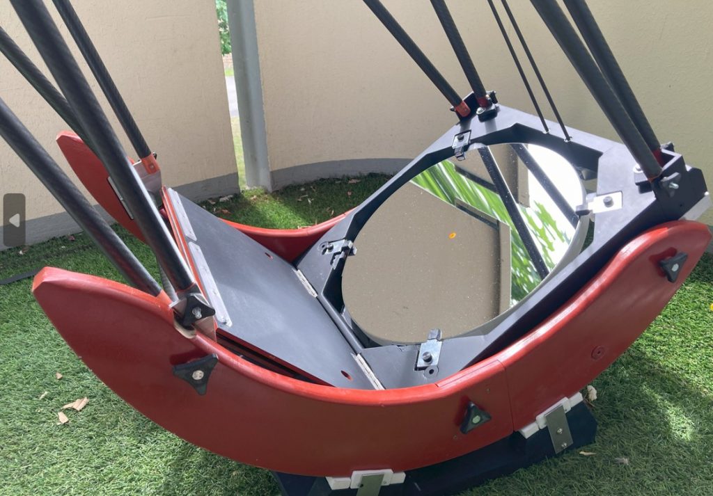
Primary structure (box)
Frame
Made from composite/carbon/fiberglass: PVC foam panels pre-laminated, cut to size, epoxy-glued, then vacuum-laminated with 120 g/m² fiberglass. Surfaces smoothed with green auto‑body filler for perfect paint finish
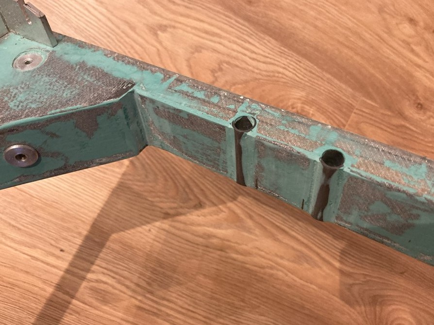
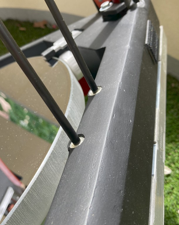
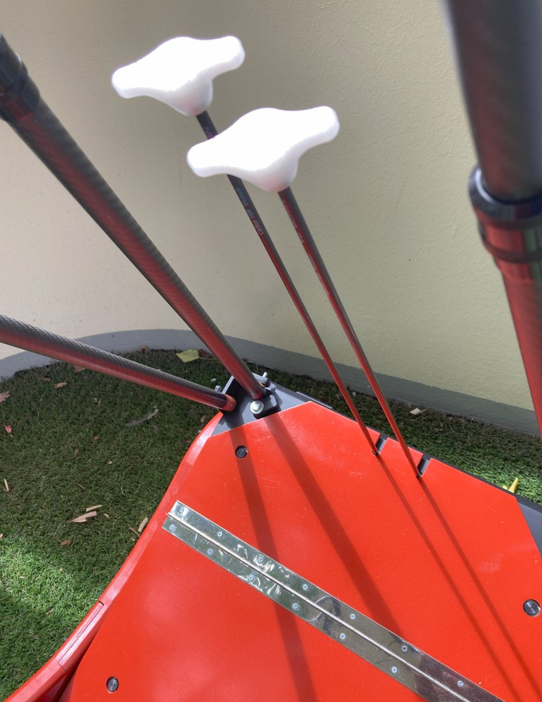
Two carbon tubes are installed on the rear wall for collimation rod passage—these tubes are aligned with the adjustment screws.
The tubes are mounted via embedded/collapsed brackets; an extra screw was added during bonding for alignment precision.
A 3D‑printed knob prevents movement of the 6 kg, 25 mm thick mirror during transport by supporting anti‑tilt shims.
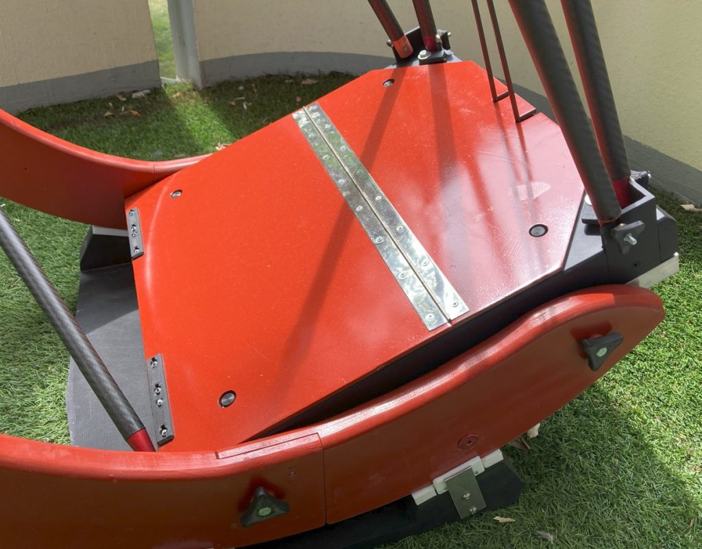
Lid
Hinged between the rocker’s trunnions. Divided into two unequal parts, resting on the cross tube between the trunnions.
Originally intended to stiffen the trunnions, but as they are in two pieces, they lacked rigidity. Triangulation was therefore added between them.
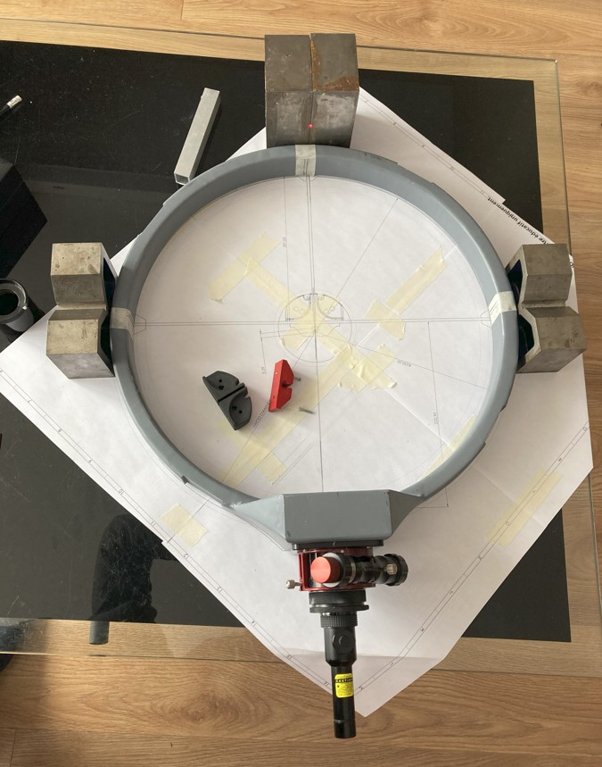
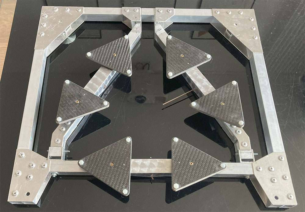
Mirror cell
Frame
Reuse of Serge’s T400‑C design: 20 mm aluminium frame with two levers and a crosspiece, each bearing a balance with 2 triangles.
The cell is screwed vertically into the primary box at each corner.
Balances
Triangles made from composite: balsa + 3 plies of 200 g carbon each side of 4 mm board.
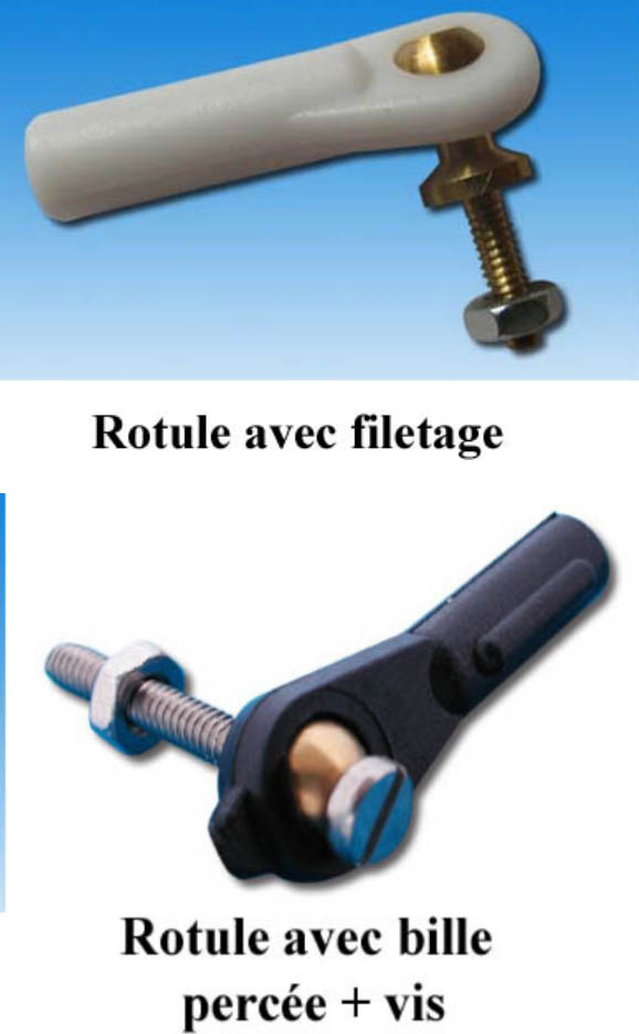
Two ball-rotule types tested:
Hollow bead ball with M3 screw: compact, but requires a wide conical hole for the screw head.
Second model simpler and easier to glue.
Mirror lateral tabs
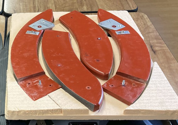
Trunnion
Cutting
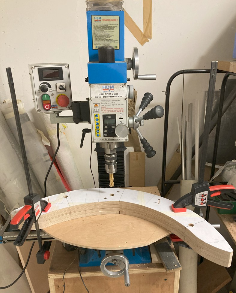
Made of 15 mm birch plywood in two pieces. For precise cutting, the plan was double‑faced‑taped directly to the plywood.
The assembled thickness surface was dressed on a grinding wheel; inserts were drilled in through‑hole in one go on a milling machine.
Pins
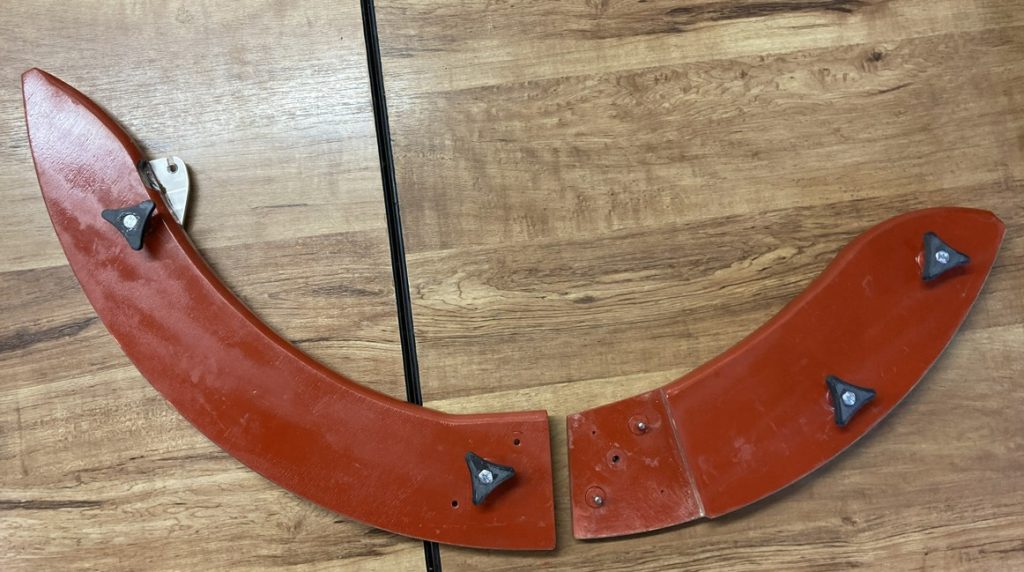
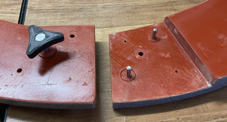
The two trunnion halves overlap by ~10 cm, joined via two dowels and a central screw.
Dowels: stainless steel rods in fitted inserts. Glue sequence: first one insert on one half, dowels in inserts, then insert on second half with fully assembled trunnion for exact fit.
Result: perfect—no play, requiring “blobloter” to separate halves.
As ebonystar is no longer available, Formica Stardust (ref. 1782‑CR‑HPL‑EDGE) was used, sourced from a UK supplier.
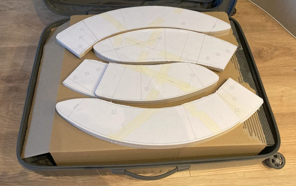
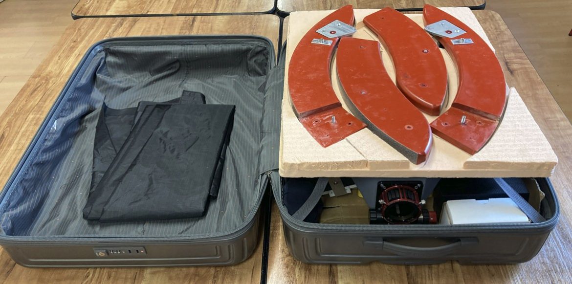
After rough cutting parts, layout inside the case was checked to ensure trunnions fit with margin.
Remaining height allowed making a 20 mm styrofoam jig for trunnion positioning to prevent shifting during transport.
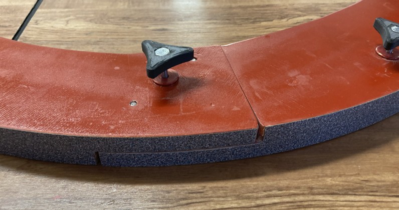
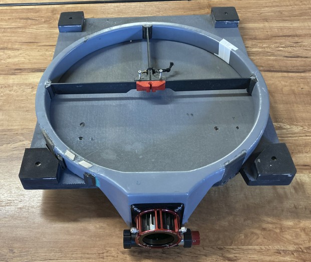
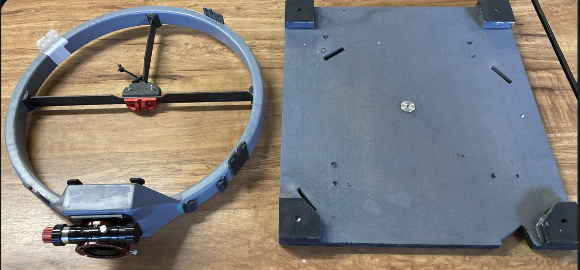
Rocker
PU foam panel sandwiched with carbon on both sides; each of the four corners has a triangle (foam/carbon) to support Teflon pads.
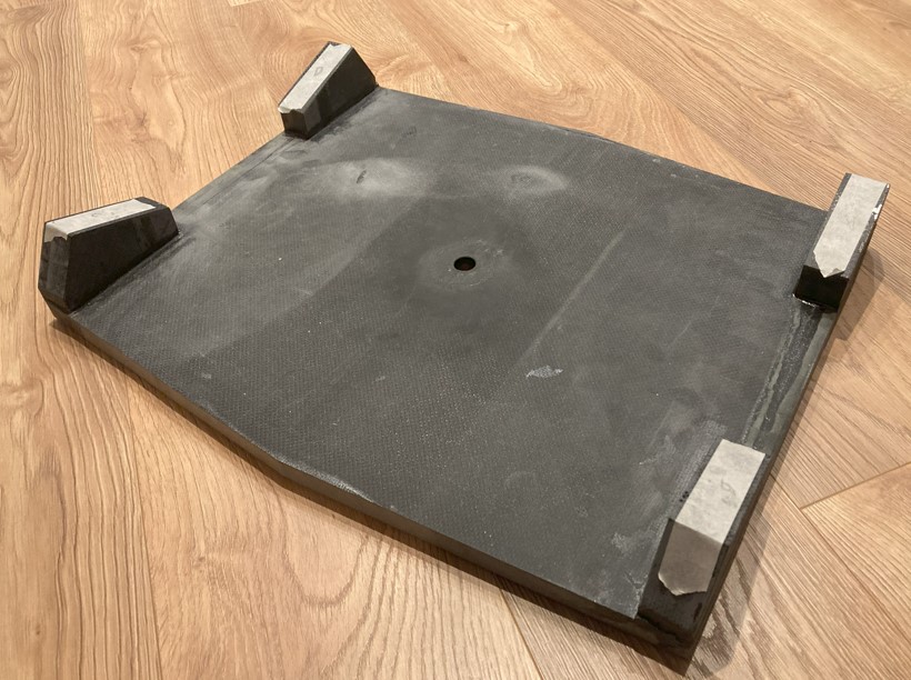
Base
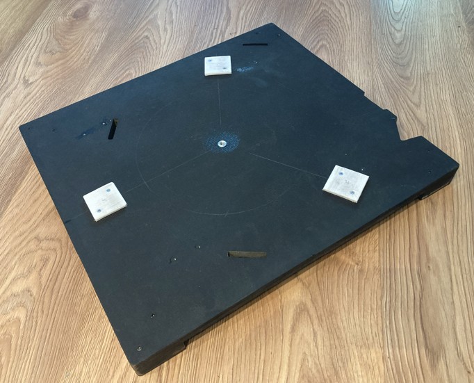
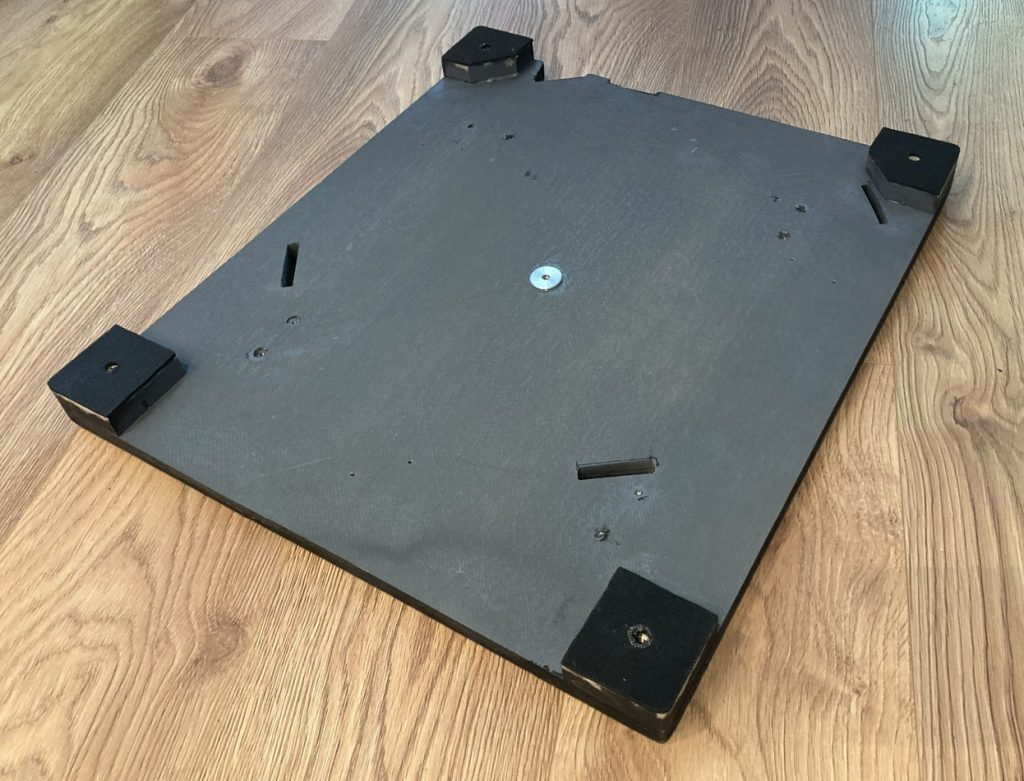
Composed of two 8 mm PU foam plates, carbon‑laminated on both faces — very stiff and flat thanks to lamination on glass.
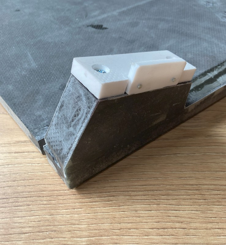
Four 18 mm birch plywood feet with inserts allow attaching adjustable feet or spikes. Hard rubber added to feet to prevent slipping. Although hyperstatic with four feet, adjustability compensates; large base fits the case and provides stability.
Rocker and base are flat and laminated on the same slab; four pads are positioned near the trunnion supports.
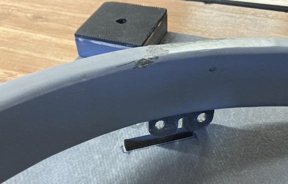
For storage, the secondary cage legs nest into slots cut in the base, securing the cage during transport.
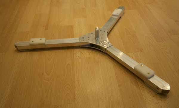
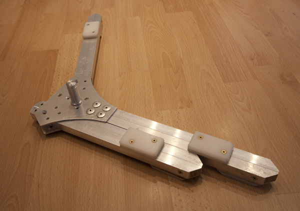
A previous star-shaped base remains an alternative (lighter, composite, but bulkier).
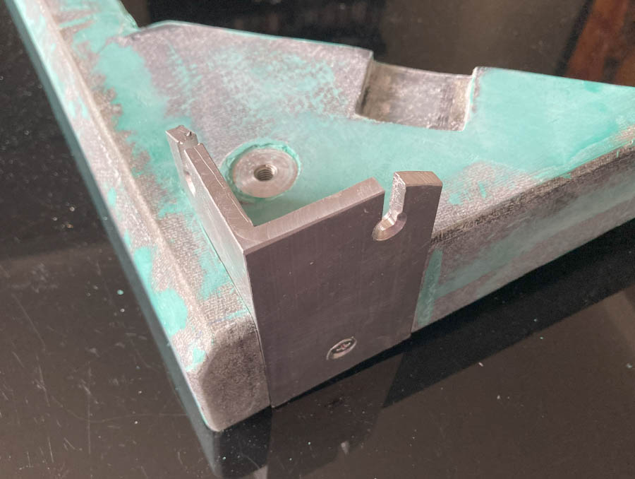
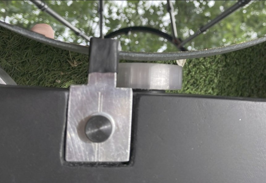
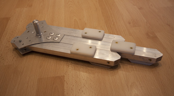
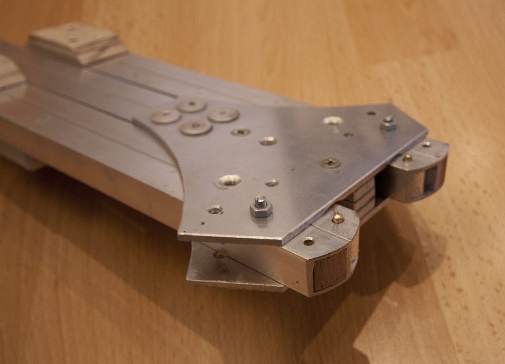
For good stability, a large base is necessary, but I want to make it fit in the box and with minimal disassembly.Based on the star base principle, one branch is fixed while the other 2 rotating branches allow it to be pressed against the sides of the first. The pivot screws onto the base.
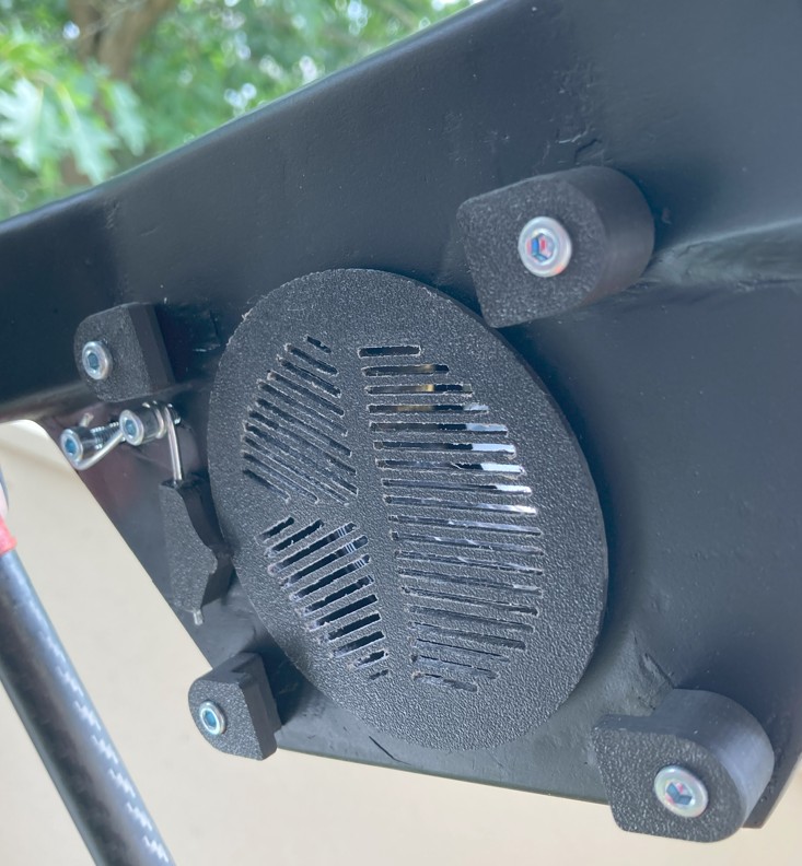
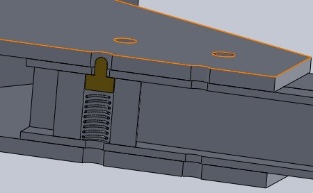
The branches are held in position by a small spring-mounted lug.This is a very simple system often found on commercially available tubular aluminum structures.Here, the system consists of a brass lug, pressed against the square tube by a spring and guided in a cylinder force-fitted into the square profile.
On my Strock250 telescope, the rocker can derail from its base in certain positions and when moving too quickly when combining altitude and azimuth. On this T400, the base is already larger, but I’m going to add a pin to secure the rocker and base. One regret… This star-shaped structure, although made of aluminum, is relatively heavy: 1.2 kg! A single-piece composite structure would have been lighter but also bulkier, and would have required redesigning the casing dimensions to achieve the same stability. To increase the telescope’s stability on grass or sloping terrain, I’m going to add screw-on spikes under the base.
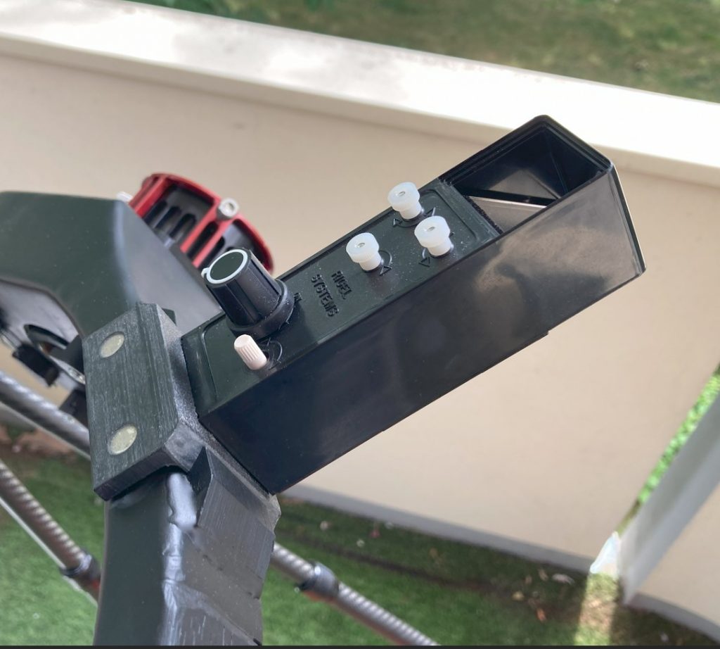
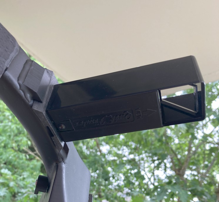
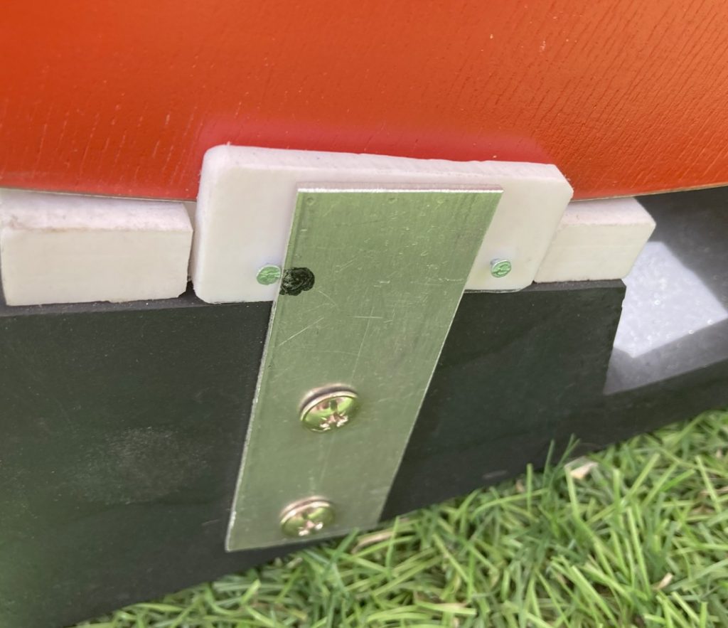
Telrad is mounted on an L‑bracket; the top part uses magnets to snap it in place.
The vertical part forms a dovetail with 3D‑printed pieces glued to the secondary cage.
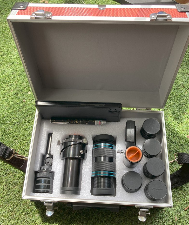
Eyepiece case
The main case was already full, so a small accessory case was made.
Originally bought a Nagler 22, but the Paracorr + Nagler 22 was too heavy compared to other eyepieces, causing balance issues. The Houdini 20 arrived and solved this: Paracorr + Nagler Type 6 vs Houdini 20 have similar masses (800 g vs 600 g).
The case includes:
Laser collimator
Paracorr type II
Houdini 20
Nagler 13
Nagler 7
Nagler 5
Nagler 3.5
Powermate 2.5×
Green laser
Memstar
9″ tablet with SkySafari
Bahtinov mask
A 3D‑printed Bahtinov mask is used inside the secondary cage in place of the filter slider.
Not sure if it will help with the A7S or ZWO, but it works.
Feedback & experience
Starting summer 2025 with intense fine-tuning and testing. First light went well.
Highlights:
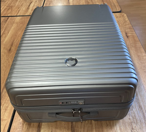
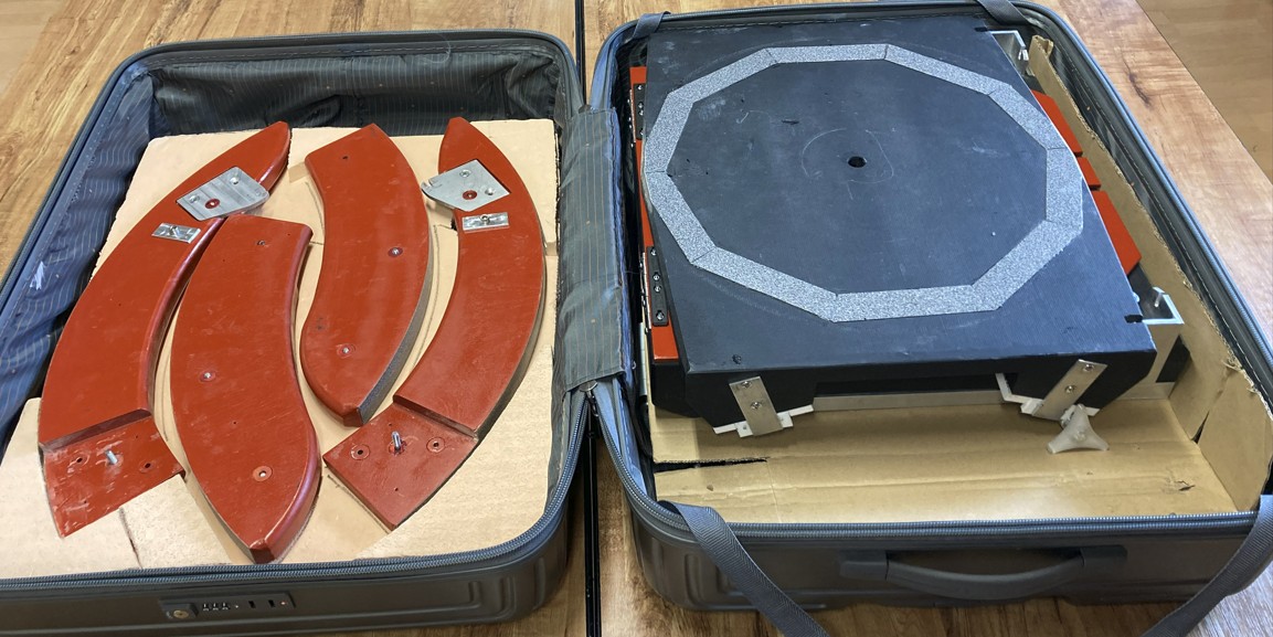
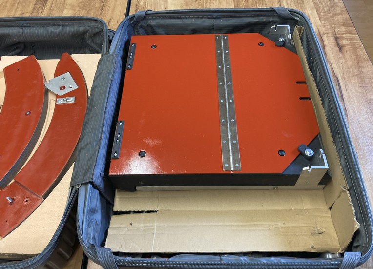
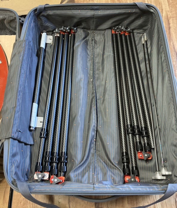
Everything fits in the suitcase.
Two-piece trunnions are stiff and assemble without play.
Collimation works very well.
Telescopic tubes maintain structural rigidity.
Telrad is well‑placed and solid.
Secondary mirror mount with elastic pivot is easier to adjust than spring‑based systems.
Houdini 20 eyepiece is timely.
Telescopic tubes are easy to adjust; only rear tubes must be exact length for collimation, with locking pins ensuring parallelism.
Remaining issues:
Some vertical vibration likely from rocker or base—they’ll test with two bases and equatorial table; possible reinforcement if rocker is at fault.
Altitude motions are good but need testing at high magnifications.
Balancing is critical: with lightweight mirror (6 kg) and heavy trunnions, natural balance occurs around 60° altitude. At horizon it holds position unassisted, but pointing at zenith requires elastic. Needs mastering.
Magnitude 78, le club d’astronomie de Saint-Quentin en Yvelines s’est spécialisé depuis plus de 30 ans dans l’observation du ciel, la construction d’instruments, le dessin, les voyages…
Nos coordonnées : Magnitude 78 (MJC Mérantaise) 6, rue Hodebourg 78114 Magny les Hameaux